Interface & commands
Loading a file: Notepad++ plugin
After installation is successful, the NCnetic plugin shows up in the Notepad++ plugin toolbar. By hitting the Plot/Refresh function, the 3D plot window appears, and the currently selected G-code/NC file is simulated. To switch files or after editing the current file, you need to hit the Plot/refresh function again in order to plot the new or modified file.
If no “Languages” (also called lexer) have been applied to the currently displayed G-code/NC file, the plugin will apply its own syntax highlighting.
Loading a file: Gcode viewer stand-alone application
After launching the application, click on the ‘Import’ button in the toolbar and select the file you want to plot.
Alternatively, drag and drop files from the Windows File Explorer.
You can also launch the standalone portable application via the command line by calling the .exe file and passing the file to plot as an argument:
Example: C:\NCneticPlayer.exe “C:\Users\MyUser\mill_pgm.nc”
3D Models
If a .STL file is present in the same folder as the NC file and shares the same name (for example: mill_pgm.nc and mill_pgm.stl), the 3D model is plotted in the 3D view alongside the NC file. Alternatively, you can drag and drop an .STL file into the 3D view to plot it.
Navigation
Selecting a move in the 3D view will jump to the corresponding line within the G-code/NC file. Selecting a text line within the G-code/NC file will select the corresponding move in the 3D interface. Additional information about the selected file and the selected move, such as coordinates, feeds, lengths, etc., are displayed in the right panel.
By dragging its handle left or right, you can show/hide the right-side panel, which provides additional details about the selected move, including length, coordinates, feed, spindle speed, and more Below the right-side panel, you’ll find buttons to execute various commands:
Below the 3D view control, you’ll find a toolbar with buttons for navigation commands, allowing you to move through the simulation steps:
- Start simulation
- Stop simulation
- Previous path
- Previous move
- Next move
- Next path
In addition, a track bar allows you to navigate through the entire file line by line.
Interaction with the 3D interface is performed through commands:
- Selection (mouse left-click by default)
- Pan (mouse middle button by default)
- Rotate (mouse right button by default)
- Go back to default view and re-center view(double-click any mouse)
In addition to mouse commands, views can be adjusted by clicking on the corresponding face on the compass (XYZ axis display) located in the bottom-right corner of the 3D view.
Toolbar
Above the 3D view control, you’ll find a toolbar, allowing you to execute special commands:
- Import: Open a file dialog to import a G-code/NC file.
- Post-process: Open the post-processor dialog. (see the post-processor page for more informations)
- Sheet CAM module: Open the SheetCAM module. (see the SheetCAM module page for more informations)
- Change reference: Select the tool and click anywhere on the current toolpath to set the new origin (X=Y=Z=0). Informations in the side panel then refer to this newly created reference. To reset, select the tool and click outside the toolpath.
- Tool database: Open the tool database dialog (see the dedicated section for more informations).
- Options: Open the options dialog (see the dedicated section for more informations).
Side Panel
The side panel displays information about the currently selected move, such as position, length, progress, and more.
Jog controls allow the user to check the current machine kinematics by moving the machine axes.
Default supported functions
Adresses
- N: Block number.
- X, Y, Z: Linear axis values (or macro inputs).
- A, B, C: Angular axis values.
- I, J, K: Arc center axis values.
- F: Feed rate.
- S: Spindle speed.
- R: Arc radius or rotation angle or drill cycle retraction value.
- L: Sub repetition or drill cylce repetition
- P: Sub number or scale factor
- T: Tool number
Gcodes
- G0: Rapid move.
- G1: Linear move.
- G2: Counter-clockwise arc.
- G3: Clockwise arc.
- G4: Dwell.
- G90/G91: Absolute/relative coordinates. 91.0 and G91.1 to for absolute / relative arc center.
- G17/G18/G19: Work plane selection (XY/XZ/YZ).
- G40/G41/G42: Tool radius compensations (None/Left/Right)
- G28: Home.
- G92: Set new reference.
- G52: Work offset / Reference shift.
- G53: Machine coordinate system.
- G54/G55/G56/G57/G58/G59: Work offset.
- G80/G81/G82/G83/G84/G85/G86/G87/G88/G89: Drill cycles.
- G50/G51: Scale program/Reset scale.
- G68/G69: Rotate program/Reset rotation
Comments
Any text following the character ; or ’ is considered a comment, as well as any text enclosed in parentheses.
Sub-programs
- Sub start: The character O followed by digits is considered a program or routine declaration.
- Sub end: M99 signals a return from a sub-program or routine, while M02 or M30 return from the main program.
- Sub call: To call a sub-program from the main program, use M98 P1234, where 1234 corresponds to the sub-program name (e.g., O1234).
Macro B
- Variables: The character # followed by digits is considered a variable. Variables can be assigned and then used for formulas and/or logic operations.
- GOTO: Jump to the target block number.
- IF: If/then logic operator.
- WHILE: While logic operator
- G65: Call a macro with input parameters.
Options & Settings
View
| Parameter | Description |
|---|---|
| Default view | Specify the default view applied after a mouse double-click or when a file is plotted. |
| Default roll | Specify the default camera roll (0°, 90°, 180°, 270°) applied after a mouse double-click or when a file is plotted. |
| Hide parts | Show/Hide parts in the 3D view. |
| Hide tools | Show/hide tools in 3d view. |
| Hide compass | Show/hide compass in 3d view. |
| Hide direction arrow | Show/hide a glyph indicating the direction of the current move. |
| Hide axis | Show/hide axis in 3d view. |
| Hide rapids | Show/hide rapid moves in 3d view. |
| Hide kinematic elements | Show/Hide the machine’s kinematic elements in the 3D view. |
| Hide stock | Show/hide the stock representation. |
Machines
| Parameter | Description |
|---|---|
| Custom Machine | The definition of the machine is derived from the “machine file”. When set to true, all machine options are retrieved from the “machine file”. |
| Machine File (Custom machine) | Path of the machine file. |
| Machine Type | Specify the kinematics of the current machine. By convention, linear axes are defined as XYZ; A represents rotation around the X-axis, B represents rotation around the Y-axis, and C represents rotation around the Z-axis. See table. |
| Rotary Z offset (Radius) | When ‘Machine Type’ is set as 4 axis ‘TABLE’ machine, it is possible to apply a Z offset representing the radius of the cylinder where the toolpath is mapped. (Z0 is on the surface of the cylinder). |
| File type | File Type to be interpreted. See table. |
| Inverted Rot 1 | Reverse the direction of the first rotation axis. |
| Inverted Rot 2 | Reverse the direction of the second rotation axis. |
Machine type
| [Type] | Description |
|---|---|
| XYZ | 3 (linear) axis machines. |
| XYZ_A_TABLE, XYZ_B_TABLE, XYZ_C_TABLE | 4-axis machines with 3 linear axis and one rotational on the workpiece. |
| XYZ_A_HEAD, XYZ_B_HEAD, XYZ_C_HEAD | 4-axis machines with 3 linear axis and one rotational on the tool holder. |
| XYZ_AB_TABLE_TABLE, XYZ_BA_TABLE_TABLE, XYZ_AC_TABLE_TABLE, XYZ_BC_TABLE_TABLE | 5-axis machines with 3 linear axis and 2 rotational axis on the workpiece. |
| XYZ_AB_TABLE_HEAD, XYZ_BA_TABLE_HEAD, XYZ_AC_TABLE_HEAD, XYZ_BC_TABLE_HEAD | 5-axis machines with 3 linear axis, one rotational axis on the workpiece and rotational axis on the tool holder |
| XYZ_AB_HEAD_HEAD, XYZ_BA_HEAD_HEAD, XYZ_AC_HEAD_HEAD, XYZ_BC_HEAD_HEAD | 5-axis machines with 3 linear axis and 2 rotational axes on the tool holder. |
File type
| [Type] | Description |
|---|---|
| GCODE_LIGHT | Simplified G-code with a limited set of commands. |
| GCODE_EXTENDED | G-code with standard commands and macros. |
| GCODE_BMACROS | G-code with macros B syntax support for parametric programming. |
| CL_DATA_FILE | APT files (position and direction vector). |
| TCP | The G-code file is interpreted as an XYZ_AC_HEAD_HEAD file, independently of the actual kinematics of the machine defined in ‘Machine Type’. |
Controls
| Parameter | Description |
|---|---|
| Selection, pan & rotation | Set of mouse buttons for selecting moves, panning the view, and rotating the view. |
| Inverted wheel | Reverse the wheel direction for zooming in and out. |
| Precise selection | Selection with the mouse lands on the exact point clicked; otherwise, the target point is selected. |
Side panel
| Parameter | Description |
|---|---|
| Side panel position | Position of the side panel. |
| Hide panel input | Show/hide the input lines (G-code/NC) of the selected move in the side panel. |
| Panel input buffer size | Number of input lines (G-code/NC) displayed in the side panel. |
| Hide panel variables | Show/hide the current values of variables (macros) for the selected move in the side panel. |
| Hide jog controls | Show/hide the jog controls toolbar. |
| XYZ jog step | Distance moved per jog input for X, Y, and Z axes. |
| Rotations jog step | Angle moved per jog input for rotational axes. |
Interface
| Parameter | Description |
|---|---|
| Simulation speed | Speed factor applied when the simulation is started. |
| Marker size | Scale of the marker/glyph size (direction arrow/compass…). |
| Theme | Select the theme. |
Remap adresses
The default addresses [X, Y, Z, I, J, K, A, B, C, F, S, R] may not be suitable for all G-code/NC files. For instance, while A typically represents rotation around the X-axis, B represents rotation around the Y-axis, and C represents rotation around the Z-axis, some CNC manufacturers may not adhere to this standard convention. In such cases, remapping the addresses can be useful.
Example:
We have G1 X100 Y50 Z20 U15 V30, where U represents the first rotation axis and V represents the second rotation axis of a 5-axis head-head machine. Addresses X, Y, and Z are standard, while U and V are specific to the machine we aim to simulate.
-> Remapping the addresses from A to U and B to V results in the correct G-code/NC interpretation.
Tool database
The interface is divided into three sections:
- Tool List: Displays the tool name, color, and station number where the tool is mounted. Use the ‘Add’, ‘Remove’, or ‘Copy’ commands to manage the tool list. Additionally, ‘Set Position’ buttons are available to quickly mount the selected tool in a station defined in the current NC file. Use ‘Set Position X’ to remove any assigned station number.
- Tool Settings: Allows configuration of all parameters for the tool selected in the tool list.
- Tool Geometry Representation: Shows a visual representation of the tool’s geometry.
Main
| Parameter | Description |
|---|---|
| Nb | The tool number or station number to be called in the NC file. |
| Type | Tool type. See the geometry section for details. The ‘Null’ tool displays a tool marker instead of actual tool geometry, while the ‘STL’ type allows loading an STL file to define the tool’s geometry. |
| Color | Tool color. |
| Name | Tool name. |
| Radius compensation | Specifies the tool radius compensation. |
| Height compensation | Specifies the tool height compensation. |
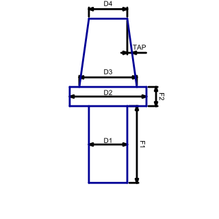
| Add tool holder | Adds a 3D representation of the tool holder when active. See the geometry section. |
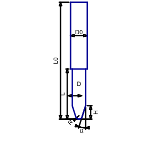
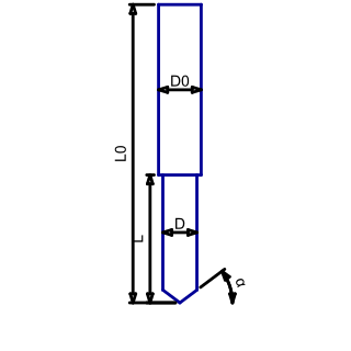
Geometry
4-axis and 5-axis
NCnetic includes all the essential tools to easily set up and simulate 4-axis and 5-axis NC files. This section covers the basic settings required to configure NCnetic for accurate simulations.
By convention, the addresses in the NC file are as follows:
- A: rotation around the X-axis
- B: rotation around the Y-axis
- C: rotation around the Z-axis
You can customize these by remapping the addresses in the options.
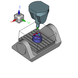
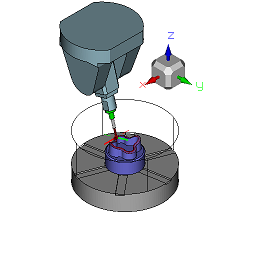
4-axis Rotary Tables
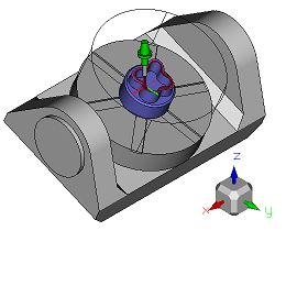
The most common type of 4-axis CNC machine has a part holder mounted on a rotary table to perform rotational machining, multi-side milling, or simply to change parts fixed on different sides of the table.
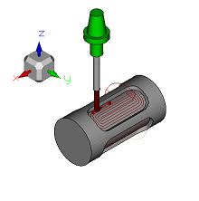
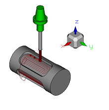
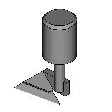
The origin of the Z-axis (Z=0) may coincide with the rotation axis (‘Rotary Z offset radius’=0, the default setting), or be on the surface of the part. In the latter case, the radius of the cylindrical part must be entered in ‘Rotary Z offset radius’.
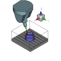
4-Axis Tool tilting
This configuration often corresponds to a choice of toolpath representation rather than an actual hardware feature (although such machines do exist). In this case, the rotation values represent a tilt of the tool rather than the rotation of the part. The advantage of this notation is that the XYZ values for the tool position remain unaffected by the rotations.
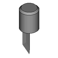
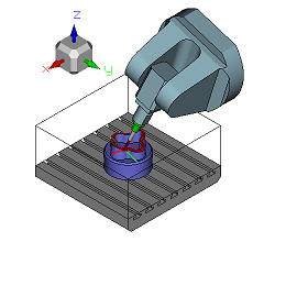
“Tangential” tools
The ‘XYZ_C_HEAD’ configuration of a 4-axis machine is used when the rotation of the tool around its own axis is critical. A common example is tangential knife or blade cutting, where the cutter must be oriented in the direction of tool travel to cut the material accurately.
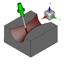
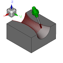
5-axis
5-axis CNC machines are designed so that, in addition to the three translational movements, two rotational movements allow the tool to be oriented in any direction. These rotations may affect either the part being machined, as in the table-table configuration; the tool, as in the head-head configuration; or one on each, as in the table-head configuration.
For a quick setup, set the ‘Machine Type’ option in the options to match your configuration. Use the ‘Include Sample’ flag to add a simplified 3D model of the kinematic chain for the current machine type. The ‘Inverted Rot’ option allows you to reverse the direction of a rotation axis, so that a positive angle results in a counterclockwise movement, or vice versa.
TCP mode
TCP mode is a special representation of tool orientation that can be activated with the ‘File Type’ option. In this mode, the content of the NC file is interpreted as though the machine operates in a head-head AC configuration, using azimuth and inclination angles, regardless of the machine’s actual kinematic chain. The advantage of this notation is that the XYZ values for tool position remain unaffected by the rotations.