The nesting module allows users to import DXF files, perform basic nesting, and generate toolpaths for 2D CNC cutting machines such as plasma cutters, laser cutters, oxy-fuel cutters, or waterjets.
The dialog window is integrated within the NCnetic interface (standalone or as a Notepad++ plugin) and contains a Preview panel and a tab control.
The ‘Run Nesting’ command executes the nesting algorithm using the inputs provided in the various tabs. The ‘Export DXF’ command opens a save file dialog to export the currently previewed shape or nesting. The ‘Generate Toolpath’ command creates the toolpath for the currently previewed shape or nesting and loads it into the NCnetic interface.
To export your machine G-code or NC file, use the Post-Processor module.
Any changes in the part or sheet list will reset the nesting results, which must be rerun to apply the modifications.
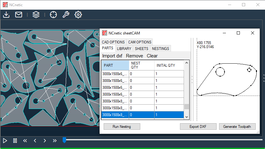
Parts tab
The Part tab allows users to import DXF geometries and set their quantities for nesting.
Click ‘Import DXF’ to open a file dialog and select the DXF files to import. If a DXF contains multiple parts, they are automatically divided into separate entries. If the imported DXF is organized into layers, a Layer Settings popup will appear.
Double-click an entry in the part list to set the initial quantity of a part.
Select a part and click ‘Remove’ to delete it, or click ‘Clear’ to remove all parts.
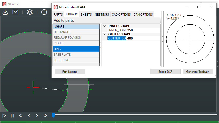
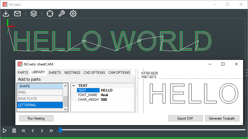
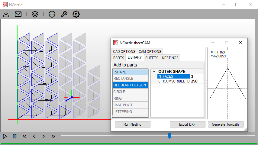
Library tab
The Library tab provides access to a standard set of parameterizable shapes.
Click ‘Add to Parts’ to add the selected shape to the part list.
Sheet tab
The Sheet tab contains the list of available sheets for nesting.
Click “Add” to create a new sheet with default parameters from the CAD Options tab (length, width, and quantity).
Double-click an entry in the sheet list to set the length, width, and initial quantity of a sheet.
Select a sheet and click ‘Remove’ to delete it, or click ‘Clear’ to remove all sheets.
The “Load Nesting DXF” command allows you to load one or more existing nestings in DXF format. The sheet width and length are set using the default parameters from the CAD Options tab. This function lets you add new parts from an existing nesting or simply generate a toolpath from an imported part or nesting.
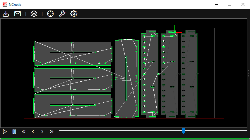
Nesting tab
The Nesting tab displays the results of the current nesting calculation.
CAD options tab
DXF import:
| Parameter | Description |
|---|---|
| Merge distance | Maximum distance between vertices to automatically merge overlapping points. |
| Link distance | Maximum distance to consider separate lines as connected for path creation. |
| Set new origin | Sets the origin of the imported DXF to a new point (0,0) or custom coordinates. |
| Merge layers | Combines multiple layers from the DXF into a single layer for processing. |
Material:
| Parameter | Description |
|---|---|
| Origin | Defines the reference point of the sheet for nesting (or the imported part if ‘set new origin’ is active). |
| Margins | Minimum distance to leave between sheet edges and parts. |
| Part spacing | Minimum distance to leave between individual parts in the nesting. |
| Default sheet width | Width of the sheet used by default when creating new sheets. |
| Default sheet height | Height of the sheet used by default when creating new sheets. |
| Default sheet quantity | Default sheet quantity when adding new sheets. |
Nesting:
| Parameter | Description |
|---|---|
| Rotations | Allowed rotations for parts during nesting. |
| Min internal areas | Minimum area inside parts that are considered for nesting. |
| Pave limit | If a part’s actual area represents more than this percentage of its bounding box area, the nesting algorithm treats the part as its bounding box for faster computation. |
CAM options tab
Offsets:
| Parameter | Description |
|---|---|
| Tool radius compensation | Distance added or subtracted to account for the cutter radius in the toolpath. |
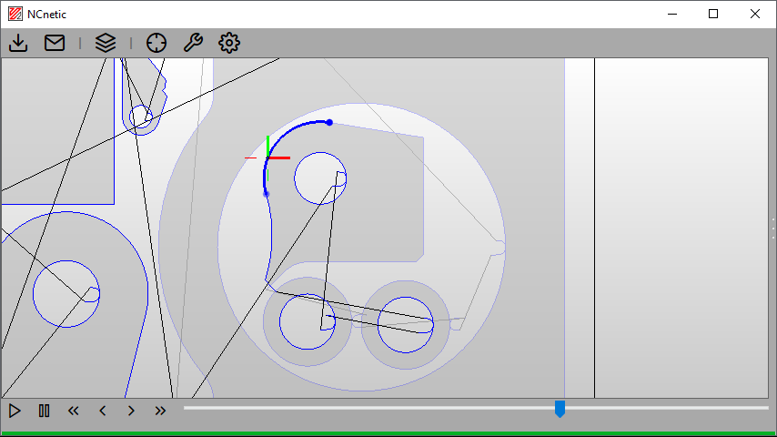
Leads:
| Parameter | Description |
|---|---|
| Position | Where the lead-in and lead-out are prefered. |
| Lead-in length | Linear length of the lead-in segment before cutting the part. |
| Lead-in radius | Radius of the curve connecting the lead-in to the cut. |
| Lead-out length | Linear length of the lead-out segment after cutting the part. |
| Lead-out radius | Radius of the curve connecting the lead-out to the cut. |
| No arcs in corners | Enables straight lead-ins and lead-outs in corners (instead of arcs). |
| Lead-in length (no arcs) | Length of the straight lead-in in corners. |
| Lead-out length (no arcs) | Length of the straight lead-in in corners. |
Gallery: